版本 17a8623641d7aee549ec45c8ad497bf1486a2f08
Changes from 17a8623641d7aee549ec45c8ad497bf1486a2f08 to current
---
title: Real-time Clock (RTC)
categories: GPIO, STM32, STM32F4
...
Introduction
==============
Real-Time Clock(RTC)是負責記錄時間的元件,出現在需要長期使用時鐘的電子設備中。例如學校定時關閉冷氣的裝置,以及手機上的鬧鈴功能。
System Overview
-----------------
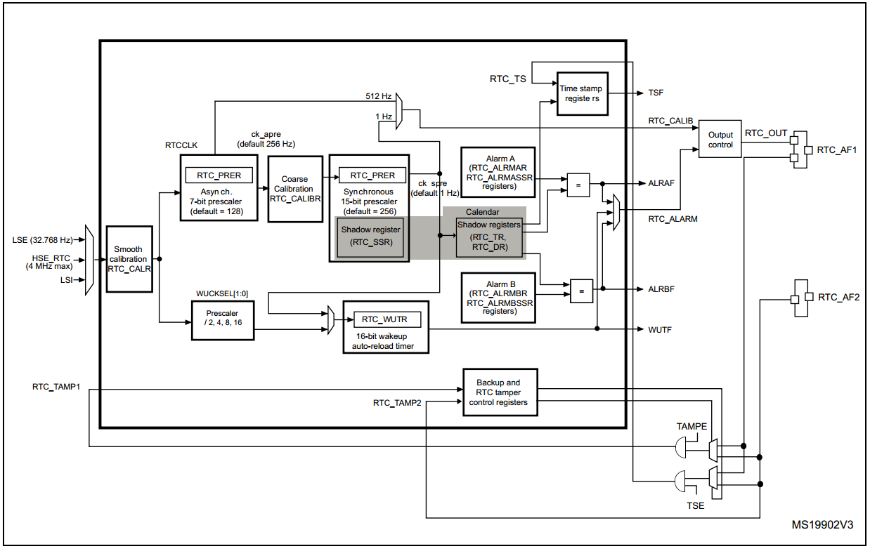
基本上RTC(Real-time clock)本身就是一個真正的時鐘,利用原本STM本身所內建的振盪器再利用Prescaler降成1Hz讓RTC使用。利用硬體達成的binary-coded decimal (BCD) format,可以把下列與時間有關的資訊儲存,而且不需要任何軟體轉換,因為硬體就已經把資料轉成一般的日期格式。
- sub-seconds
- seconds
- minutes
- hours in 12-hour or 24-hour format
- day of the week (day)
- day of the month (date)
- month
- year
可用的功能
- Alarm A & Alarm B
- Auto wakeup
- Timestamp
- Tamper detection
Block Diagram
--------------------
.. image:: /rtc_block.png
[#]_
.. [#] [Block Diagram ](http://www.st.com/st-web-ui/static/active/en/resource/technical/document/reference_manual/DM00031020.pdf) p.780
Functional Description
============================
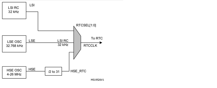
Clock Source
--------------------
.. image:: /clocksource2.png
**STM32的 Clock 有分成「SYSCLK」和「RTCCLK」:**
**STM32的 Clock 有分成「SYSCLK」和「Secondary Clock」:**
SYSCLK為系統的clock有三種來源:
1. **HSI** (High-Speed Internal) :16MHz,RC電路
2. **HSE** (Low-Speed External):4-26MHz (一般選用8MHz),石英震盪
2. **HSE** (High-Speed External):4-26MHz (一般選用8MHz),石英震盪
3. Main **PLL** clock
RTCCLK為設備的clock有兩種來源:
Secondary Clock:
1. **LSI** (Low-Speed Internal) :40kHz,RC電路震盪
2. **LSE** (High-Speed External):32.768kHz,石英震盪
2. **LSE** (Low-Speed External):32.768kHz,石英震盪
----> RTC 主要是使用 **HSE** , **LSI** , **LSE** 三種來源
----> RTC 主要是使用 **HSE** , **LSI** , **LSE** 三種來源 [#]_
*參閱reference manual p.150*
.. [#] [Clock Source ](http://www.st.com/st-web-ui/static/active/en/resource/technical/document/reference_manual/DM00031020.pdf) p.150
-----------------------------------------------
-------------------------------------------------------------------------------------------------
**比較 「HSE」, 「LSI」 , 「LSE」三種輸入來源:**
- HSE - 較為耗能, 可以處理像是USB或TV訊號的clock,需要和和另一個clock穩定同步。
- LSI - 是一個低功耗的clock,可以再停機或待機模式下保持運行,用在auto-wakeup(簡稱AWU)與 watchdog看門狗(簡稱IMDG)。
- LSE - 它是一個低功耗且"精準"的clock,適合用在時間的精確計算。
- HSE - 較為耗能, 可以處理像是USB或TV訊號的clock,需要和另一個clock穩定同步。
- LSI - 是一個低功耗的clock,可以在停機或待機模式下保持運行,用在auto-wakeup(簡稱AWU)與 watchdog看門狗(簡稱IWDG)。
- LSE - 它是一個低功耗且精準的clock,適合用在時間的精確計算。
Prescaler
--------------------
.. image:: /RTC_Prescalers.png
RTC prescaler.png
``ck_spre``一般而言要降為1Hz的頻率,因為省電的因素STM設計了兩個Prescaler。7 bit非同步prescaler(``PREDIV_A``)和15 bit同步的prescaler(``PREDIV_S``)。這兩個prescaler要在RTC_PRER的暫存器設定。*ST在Reference有說明當兩個Prescaler都使用時,建議讓非同步的Prescaler讓他有較大的值,以讓系統更省電*
所以``ck_spre``與兩個prescaler的關係為:
.. image:: /ck_spre2.png

例如:
LSE: 32.768kHz / (127+1) / (255+1) = 1Hz
LSE: 32.768kHz / (**127**+1) / (**255**+1) = 1Hz
LSI: 32kHz / (127+1) /(249+1) =1Hz
LSI: 32kHz / (**127**+1) /(**249**+1) =1Hz
Alternate Function RTC Outputs
--------------------------------------
[#]_
Alternate function 可以將RTC某些功能對應到輸出的接腳(GPIO Pin),這些輸出可以被選擇成**tamp event** 或 **time stamp event**,
.. [#] [prescaler ](http://www.st.com/st-web-ui/static/active/en/resource/technical/document/reference_manual/DM00031020.pdf) p.781
甚至RTC Calibration 的訊號都可以藉由這個功能輸出。
-------------------------------------------
可以選擇兩個輸出:
Calibration
-----------------------------
輸出接腳 **RTC_AF1(PC13)** :
RTC裡面有兩個校正功能,一個是coarse calibration另一個是smooth calibration。[#]_
- RTC_ALARM output: 1. RTC Alarm A 2. RTC Alarm B 3. RTC Wakeup
.. [#] [Calibration ](http://www.st.com/st-web-ui/static/active/en/resource/technical/document/reference_manual/DM00031020.pdf) p.787
- RTC_CALIB output
這兩個校正不能同時被使用,而前者只能固定修正,後者則可以動態的校正。後者也可以較大範圍及更精準的校正。
- RTC_TAMP1
**1、RTC coarse calibration :**
- RTC_TS
- 被使用在補償石英震盪器的校正。
輸出接腳 **RTC_AF2 (PI8)** :
- 在非同步分頻器(ck_apre)的輸出,藉由增加或減少時間的週期達到校正,最大範圍的校正為63ppm~126ppm。
- RTC_TAMP1
- 只能在初始化Calendar時候修改,是一個**開迴路控制**(opened loop control)(又稱非回授控制系統)。
- RTC_TAMP2
- 可以利用AFO_CALIB去計算clock deviation。不能以圖中512Hz的訊號去確認coarse calibration的輸出結果,只能使用ck_spre確認校正的結果。
- RTC_TS
- reference clock calibration 和 coarse calibration 不能同時使用。
*Reference Manual p.277*
-----------------------------------------------------------------
*PI8接腳參考: datasheet p.10*
cal.png
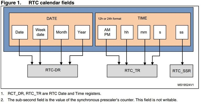
RTC Calendar
--------------------
**2、RTC smooth calibration:**
- 可以補償石英震盪器的偏差,此偏差可能是晶體老化或者溫度所造成。
.. image:: /RTC_calendar.png
- 利用每個RTCCLK pulse為單位做出小幅調整,來修正RTC的clock頻率。
- 最大範圍的校正為-487.1ppm~+488.5ppm。
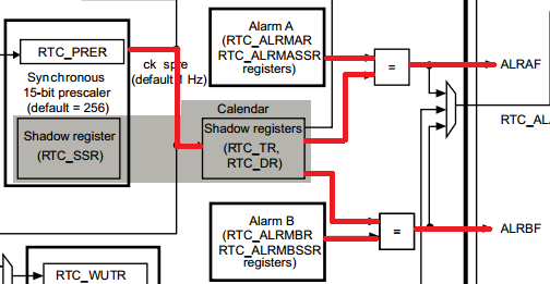
**讀取Calendar**
- 與coarse calibration不同,是屬於**閉迴路控制**(closed loop control)(又稱回授控制系統)。
- 可以使用AFO_CALIB來計算時間偏差,而且可直接檢查512Hz和1Hz的校正輸出。
當在讀取Calendar時其實並不是真正直接讀取calendar register,其實是讀**shadow register**,
----------------------------------------------------------------------------
如果想要直接讀取calendar必須要設``BYPSHAD`` 控制位元為1(在``RTC_CR`` register)才能繞過shadow register
而直接讀取calender register,通常初始化和讀取的動作採用Shadow Register。
cal.png
-----------------------------
**3、RTC reference clock detection:**
Calibration
-----------------------------
- 利用外部時鐘校正,其時鐘源必須要比LSE的時鐘還精準。[#]_
RTC裡面有兩個校正功能,一個是RTC coarse calibration另一個是RTC smooth calibration。
.. [#] [RTC reference clock ](http://www.st.com/st-web-ui/static/active/en/resource/technical/document/reference_manual/DM00031020.pdf) p.786
**1、RTC coarse calibration :**
RTC Calendar
--------------------
- coarse calibration 被使用在補償石英震盪器的校正。
- 在非同步分頻器(ck_apre)的輸出,藉由增加或減少時間的週期達到校正,最大範圍的校正為63ppm~126ppm。
- 可以使用AFO_CALIB來計算時間偏差,並更新calibration方塊圖的1Hz(ck_apre)輸出。
- 在512Hz時,並不能去檢查校正結果,只能檢查經過calibration方塊圖的1Hz(ck_apre)輸出。
**讀取Calendar:**
- 完整的校正週期要持續64分鐘。
當在讀取Calendar時其實並不是真正直接讀取calendar register,其實是在讀shadow register,如果想要直接讀取calendar必須
- 只能在初始化Calendar時候修改,不能在RTC開啟的時候修改。導致不可校正動態的誤差,只能校正固定的誤差,是一個非回授控制系統(opened loop control)。
要設BYPSHAD控制位元為1(在RTC_C Rregister)才能繞過shadow register而直接讀取calender register。
- reference clock calibration 和 coarse calibration 不能同時使用。
**Shadow Register:**
- 通常初始化和讀取的動作採用Shadow Register。
.. image:: /coarse cal.png
- 每兩個RTCCLK時間週期,RTC的calendar register (RTC_SSR, RTC_TR, and RTC_DR)的值會被自動更新到Shadow Register。
**2、RTC smooth calibration:**
[#]_
- smooth calibration 利用每個RTCCLK pulse為單位做出小幅調整,來修正RTC的clock頻率。
.. [#] [Calendar ](http://www.st.com/st-web-ui/static/active/en/resource/technical/document/reference_manual/DM00031020.pdf) p.780
- 最大範圍的校正為-487.1ppm~+488.5ppm。
-----------------------------
- smooth calibration 可以補償石英震盪器的偏差,此偏差可能是晶體老化或者溫度所造成。
- 可以使用AFO_CALIB來計算時間偏差,而且可直接檢查512Hz和1Hz的校正輸出。
- 可使用RTC_CALR register裡面的CALP和CALM去增加或減少pulses。
- smooth calibration可配置8秒、16秒、32秒的校正視窗,沒設定的情況下為32秒的視窗。
Alternate Function Outputs & Inputs
------------------------------------------
- 與coarse calibration不同,可藉由AFO_CALIB得到時鐘的偏差值(clock deviation)。這種方法可以確認修正的結果,是一個閉迴路的控制系統(closed loop control)。
Alternate function 可以將RTC某些功能對應到輸出的接腳(GPIO Pin),這些輸出可以被選擇成**tamp event** 或 **time stamp event**,
- smooth calibration可以使用在:
甚至RTC Calibration 的訊號都可以藉由這個功能輸出。 [#]_
1.AFO_CALIB (512 Hz or 1 Hz)。 2.sub-second alarms。 3.Wakeup timer。
可以選擇兩個輸出:
.. image:: /smooth cal.png
- 輸出接腳 **RTC_AF1(PC13)** :
**3、RTC reference clock detection:**
- RTC_ALARM output: 1. RTC Alarm A 2. RTC Alarm B 3. RTC Wakeup
- 利用外部時鐘校正,其時鐘源要比LSE的時鐘還精準。
- RTC_CALIB output
*原文:The reference clock (at 50 Hz or 60 Hz) should have a higher precision than the 32.768 kHz LSE clock.*
- RTC_TAMP1
---------------------------------------------------
- RTC_TS
- 輸出接腳 **RTC_AF2 (PI8)** :
- RTC_TAMP1
- RTC_TAMP2
- RTC_TS
.. [#] [Alternate Function Outputs & Inputs ](http://www.st.com/st-web-ui/static/active/en/resource/technical/document/reference_manual/DM00031020.pdf) p.227
*PI8接腳參考: datasheet p.10*
Low Power Modes
--------------------
-------------------
- RTC 設計為最小的耗能,在休眠模式下,RTC將繼續動作。
- RTC 設計為最小的耗能,在休眠模式下,RTC將繼續動作。 [#]_
- 當clock 的來源是LSE 或 LSI,在停止模式與待機模式下,RTC仍然活躍的動作。
- 在低功率( low power mode)模式下,Alarm, tamper event, time stamp event, and wakeup 依然會被中斷所啟動。
.. image:: /RTC in low power mode.png
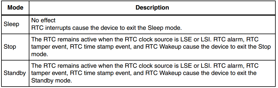
**比較三種低功耗**
- **睡眠模式(sleep mode)**:CPU停止工作,週邊設備繼續工作。
- **停機模式(stop mode)**:CPU停止工作,HSI、HSE進入關閉模式,STM32工作狀態仍然保留。(RTC正常運行)
- **待機模式(standby mode)**:STM32所有SRAM與暫存器內容,全部遺失(RTC正常運行)從待機模式喚醒相當於重新復歸。
**電流消耗**
- 一般運行模式 : 8.5mA
- 低功耗模式
- 睡眠模式 : 0.5mA
- 停機模式 :24uA
- 待機模式:2uA
.. [#] [Low Power Modes ](http://www.st.com/st-web-ui/static/active/en/resource/technical/document/reference_manual/DM00031020.pdf) p.126
---------------------------------------------------
---------------------------------------------------
Interrupt Application
==========================
Alarm
---------------------------
calendar register與alarm作比較,如果相同則將對應的flag拉起來。
- 有兩個時鐘Alarm A及Alarm B,可以當作鬧鐘使用。而且相關的register也都會有兩組。[#]_
.. image:: /embedded/RTC/alarm_pass.png
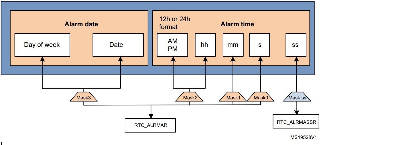
- 可利用Mask達成不同時間的鬧鈴效果。
---------------------------
- 以設定來說,生效的時候會透過EXTI_Line17的外部中斷RTC Alarm,讓ALRAF(ALRBF)的bit設成1 (Reference Manual p.380)
-----------------------------------------------
.. [#] [Alarm ](http://www.st.com/st-web-ui/static/active/en/resource/technical/document/reference_manual/DM00031020.pdf) p.781
**利用MSKx bits設定遮罩改變Alarm的行為:** [#]_
As an example, to configure the alarm time to 23:15:07 on Monday (預設MSK是0000)
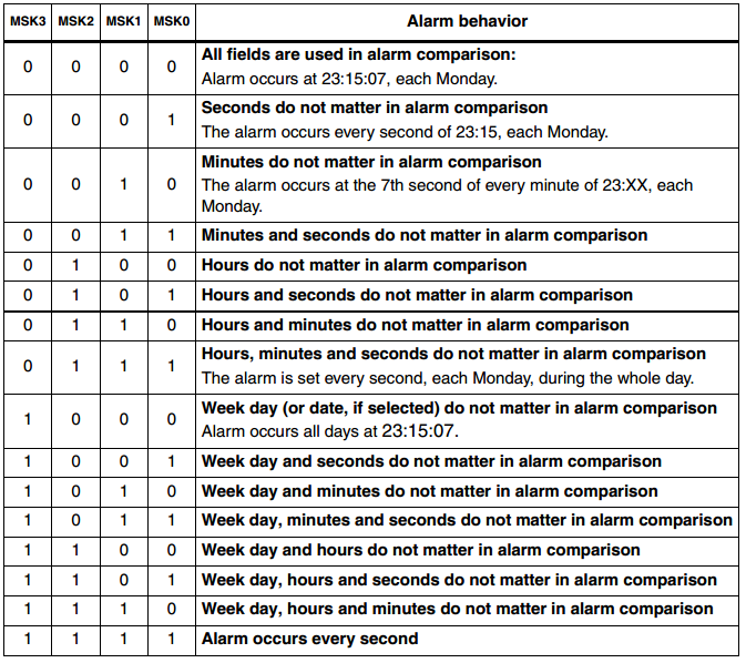
.. [#] [Alarm application note ](http://www.st.com/st-web-ui/static/active/cn/resource/technical/document/application_note/DM00025071.pdf) p.11
------------------------------------------------------------------------------------------
Periodic Wakeup Unit
----------------------------
- 周期性的喚醒(wakeup)可以達成類似一個定時倒數的timer,一個downcounting且會auto-reload 的timer。當它的counter數到0的時候,在打開中斷的情況下會定時觸發中斷。
- 與Alarm不同,Wakeup是定時觸發中斷,Alarm則是在特定時間才會觸發。
- 會有兩個因素影響wakeup unit的中斷觸發週期,一個是timer儲存數字的大小,一個是clock source。
**設定wakeup period** [#]_
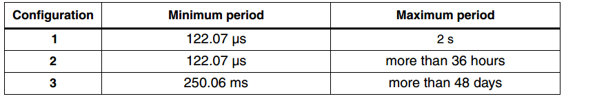
有三種組態:
Configuration 1:**short wakeup** periods
Configuration 2:**medium wakeup** periods
Configuration 3: **long wakeup** periods
**Configuration 1:**
Prescalers connected to the timebase/wakeup unit
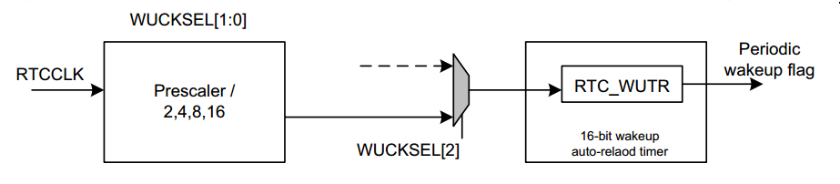
在這個設定中,wakeup unit,會接受由RTCCLK再經過Prescaler的clock。RTC_WUTR(RTC Wakeup Timer Register)為一個
auto-reload的down counting timer,這表示當使用者在初始化時設了一個值x,會在x數到0的時候觸發wakeup flag。
**EX:**當RTCCLK= 32768 Hz,代表著最小的timebase resolution為61.035μs(數一次的時間),最大則是488.28 μs。
- 所以這代表著最小可觸發wakeup flag時間為**(0x0001 + 1) x 61.035 μs = 122.07 μs**
- 最大可觸發wakeup flag時間為 **(0xFFFF+ 1) x 488.28 μs = 2 s**
*註:STM32禁止timer初始值設為0*
----------------------------------------------------------------------------
Prescalers connected to the wakeup unit for configurations 2 and 3
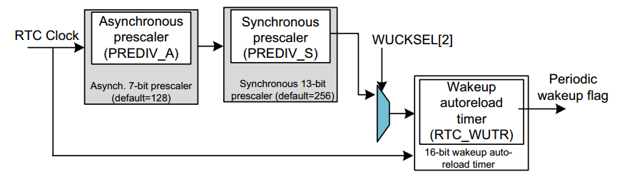
2和3的clock source相同,都是用來計算calendar的ck_spre。
**Configuration 2:**
- The minimum timebase/wakeup period is **(0x0000 + 1) x 61.035 µs = 122.07 µs.**
- The maximum timebase/wakeup period is**(0xFFFF+ 1) x 32 s = 131072 s (more than 36 hours).**
**Configuration 3:**
其Clock Source與 Configuration 2 一樣,差在2最大可以從0xFFFF倒數至0x0000,3則是0x1FFFF至0x00000
- The minimum timebase/wakeup period is: **(0x10000 + 1) x 61.035 µs = 250.06 ms**
- The maximum timebase/wakeup period is: **(0x1FFFF+ 1) x 32 s = 4194304 s (more than 48 days).**
Min. and max. timebase/wakeup period when RTCCLK= 32768Hz
.. [#] [Periodic Wakeup Unit ](http://www.st.com/st-web-ui/static/active/en/resource/technical/document/reference_manual/DM00031020.pdf) p.782
--------------------------
Time-stamp Function
--------------------------
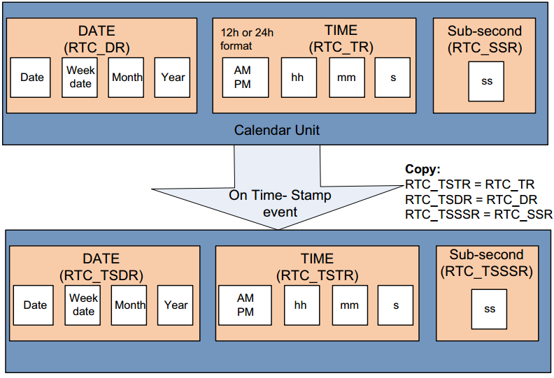
實體世界裡有「郵戳為憑」來證明信件的時間,在網路世界裡如何來證明電子文件或交易的時間?
利用Time-stamp function 可以為任何電子文件或電子交易提供準確的時間證明,並且驗證其內容自蓋上時戳後是否曾被人修改過。[#]_
Time-stamp function 提供自動幫你儲存日曆的功能
**RTC_TSDR register** : 會去讀取RTC_DR 裡面的年、月、日、周的資料並儲存
**RTC_TSTR register** : 會去讀取RTC_TR 裡面的秒、時、分的資料並儲存
**RTC_TSSR register** : 會去讀取RTC_SSR 裡面的Sub-second 的資料並儲存
.. [#] [Time-stamp Function](http://www.st.com/st-web-ui/static/active/en/resource/technical/document/reference_manual/DM00031020.pdf) p.790
-----------------------------------------------------------------------------------------------
Tamper Detection Function
---------------------------------
Tamper Detection是一個可以檢測系統是否有被竄改的功能。在Tamper發生時,RTC Backup Register會全部自動reset,
Example of code
達到保護系統的作用。而也可以在Tamper發生時,讓Timestamp發生。 [#]_
**Backup registers**
在主電源 VDD(1.8~3.6V) 關掉以後,這個backup registers會動作在 VBAT (1.65~3.6V)的低功率電源( low power mode),
所以它不會被system reset重設,它只會被tamper detection重設。或者因為backup domain reset。
------------------------------------------------------------------------------------------
如先前提到的,RTC_AF1和RTC_AF2可以被對映成不同接腳的輸入(alternate function )以偵測Tamper Event。
- TAMPER1 可以被對映到: RTC_AF1(PC13) 或RTC_AF2 (PI8).
- TAMPER 2可以被對映到: RTC_TAMP2 pin(PI8).
.. [#] [Tamper Detection Function](http://www.st.com/st-web-ui/static/active/en/resource/technical/document/reference_manual/DM00031020.pdf) p.792
------------------------------------------
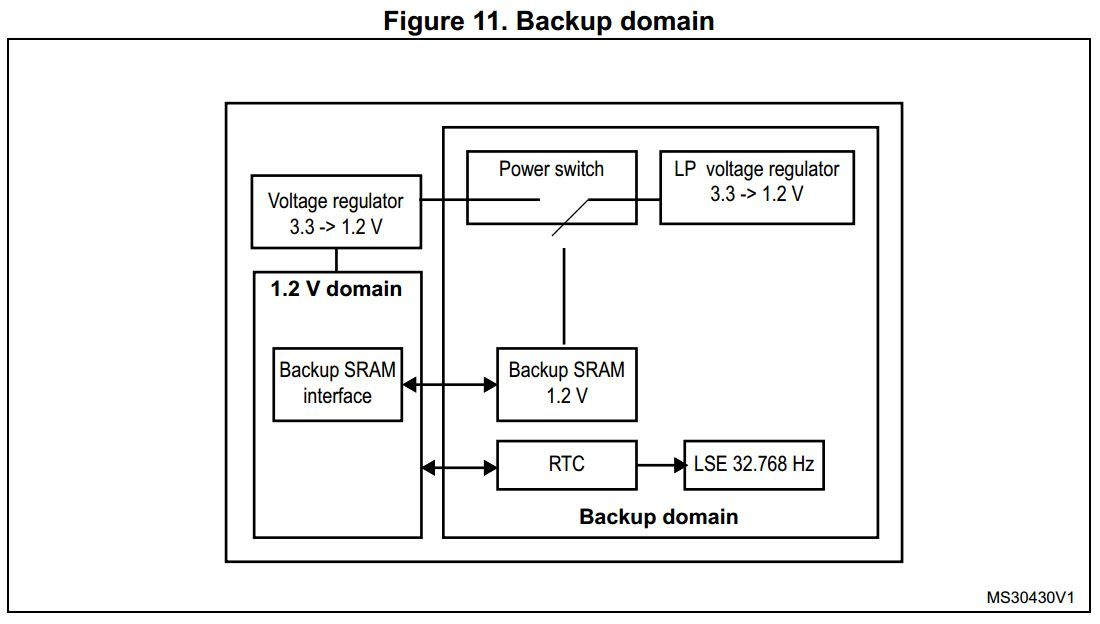
**補充 : 何謂 Backup Domain ?** [#]_
Backup Domain 有下列幾個主要裝置:
- The RTC
- The LSE oscillator
- The backup SRAM when the low power backup regulator is enabled
PC13 to PC15 I/Os, plus PI8 I/O (when available)
當VDD停止供應電源時,Backup Domain會切到standby mode的電壓,換電池供電。在reset後,RTC registers, RTC backup register and backup SRAM會被保護以避免寫入。
SRAM:靜態隨機存取存儲器(Static Random-Access Memory, SRAM)是隨機存取儲存器的一種。所謂的「靜態」,是指這種存儲器只要保持通電,裡面儲存的數據就可以恆常保。
.. [#] [Tamper Detection Function](http://www.st.com/st-web-ui/static/active/en/resource/technical/document/reference_manual/DM00031020.pdf) p.115
Example of Code
========================
下面的範例為先初始化RTC的Calendar再去設定Alarm A。一開始開機時時間為8:29:55,LED3,4,5會在開機五秒前輪流閃爍。但是在第五秒後也就是8:30:00,Alarm A觸發中斷將所有LED燈都關掉。LED6 為auto-wakeup 每秒閃爍直到alarm觸發中止。
`[ YouTube連結--實現RTC ]
<https://www.youtube.com/watch?v=SbWUkchJd-8>`_
Initialize RTC
--------------------
.. code-block:: prettyprint
RTC_InitTypeDef RTC_InitStructure;
RCC_APB1PeriphClockCmd(RCC_APB1Periph_PWR, ENABLE); /* Enable the PWR clock */
RCC_APB1PeriphClockCmd(RCC_APB1Periph_PWR, ENABLE); /* Enable the PWR clock */
PWR_BackupAccessCmd(ENABLE); /* Allow access to RTC */
RCC_LSICmd(ENABLE); /* Enable the LSI OSC */
while(RCC_GetFlagStatus(RCC_FLAG_LSIRDY) == RESET); /* Wait till LSI is ready */
RCC_RTCCLKConfig(RCC_RTCCLKSource_LSI); /* Select the RTC Clock Source */
RCC_RTCCLKCmd(ENABLE); /* Enable the RTC Clock */
RTC_WaitForSynchro(); /* Wait for RTC APB registers synchronisation */
RTC_WaitForSynchro(); /* Wait for RTC APB registers synchronisation */
/* Configure the RTC data register and RTC prescaler */
RTC_InitStructure.RTC_AsynchPrediv = 0x7F;
RTC_InitStructure.RTC_SynchPrediv = 0xF9;
RTC_InitStructure.RTC_AsynchPrediv = 127;
RTC_InitStructure.RTC_SynchPrediv = 249;
RTC_InitStructure.RTC_HourFormat = RTC_HourFormat_24;
RTC_Init(&RTC_InitStructure);
setting time
-----------------------------------------------------------------
[#]_
.. [#] [Device overview ](http://www.st.com/st-web-ui/static/active/en/resource/technical/document/datasheet/DM00037051.pdf) p.18
-----------------------------------------------------------------
Setting Time
--------------------
.. code-block:: prettyprint
/* set 8:29:55 */
RTC_TimeTypeDef RTC_TimeStruct;
RTC_TimeStruct.RTC_Hours = 8;
RTC_TimeStruct.RTC_Minutes = 29;
RTC_TimeStruct.RTC_Seconds = 55;
RTC_SetTime(RTC_Format_BIN, &RTC_TimeStruct);
/* set 8:29:55 */
RTC_TimeTypeDef RTC_TimeStruct;
RTC_TimeStruct.RTC_Hours = 0x08;
RTC_TimeStruct.RTC_Minutes = 0x29;
RTC_TimeStruct.RTC_Seconds = 0x55;
RTC_SetTime(RTC_Format_BCD, &RTC_TimeStruct);
initialize RTC alarm
Initialize RTC Alarm
--------------------
.. code-block:: prettyprint
EXTI_InitTypeDef EXTI_InitStructure;
NVIC_InitTypeDef NVIC_InitStructure;
/* EXTI configuration */
EXTI_ClearITPendingBit(EXTI_Line17);
EXTI_InitStructure.EXTI_Line = EXTI_Line17;
EXTI_InitStructure.EXTI_Mode = EXTI_Mode_Interrupt;
EXTI_InitStructure.EXTI_Trigger = EXTI_Trigger_Rising;
EXTI_InitStructure.EXTI_LineCmd = ENABLE;
EXTI_Init(&EXTI_InitStructure);
/* Enable the RTC Alarm Interrupt */
NVIC_InitStructure.NVIC_IRQChannel = RTC_Alarm_IRQn;
NVIC_InitStructure.NVIC_IRQChannelPreemptionPriority = 0;
NVIC_InitStructure.NVIC_IRQChannelSubPriority = 0;
NVIC_InitStructure.NVIC_IRQChannelCmd = ENABLE;
NVIC_Init(&NVIC_InitStructure);
--------------------------------------------------------------------
setting alarm time
-----------------------------------------------------------------------
Setting Alarm Time
--------------------
.. code-block:: prettyprint
RTC_AlarmTypeDef RTC_AlarmStructure;
RTC_AlarmCmd(RTC_Alarm_A, DISABLE); /* disable before setting or cann't write */
/* set alarm time 8:30:0 everyday */
RTC_AlarmStructure.RTC_AlarmTime.RTC_H12 = 0x00;
RTC_AlarmStructure.RTC_AlarmTime.RTC_Hours = 8;
RTC_AlarmStructure.RTC_AlarmTime.RTC_Minutes = 30;
RTC_AlarmStructure.RTC_AlarmTime.RTC_Seconds = 0;
RTC_AlarmStructure.RTC_AlarmTime.RTC_H12 = RTC_H12_AM;
RTC_AlarmStructure.RTC_AlarmTime.RTC_Hours = 0x08;
RTC_AlarmStructure.RTC_AlarmTime.RTC_Minutes = 0x30;
RTC_AlarmStructure.RTC_AlarmTime.RTC_Seconds = 0x0;
RTC_AlarmStructure.RTC_AlarmDateWeekDay = 0x31; // Nonspecific
RTC_AlarmStructure.RTC_AlarmDateWeekDaySel = RTC_AlarmDateWeekDaySel_Date;
RTC_AlarmStructure.RTC_AlarmMask = RTC_AlarmMask_DateWeekDay; // Everyday
RTC_SetAlarm(RTC_Format_BIN, RTC_Alarm_A, &RTC_AlarmStructure);
RTC_SetAlarm(RTC_Format_BCD, RTC_Alarm_A, &RTC_AlarmStructure);
/* Enable Alarm */
RTC_ITConfig(RTC_IT_ALRA, ENABLE);
RTC_AlarmCmd(RTC_Alarm_A, ENABLE);
RTC_ClearFlag(RTC_FLAG_ALRAF);
-----------------------------------------------------------------
complete code
RTC_Alarm_IRQHandler
--------------------
.. code-block:: prettyprint
vTaskSuspend( pvLEDTask );
RTC_ClearITPendingBit(RTC_IT_ALRA);
EXTI_ClearITPendingBit(EXTI_Line17);
STM_EVAL_LEDOff(LED4);
STM_EVAL_LEDOff(LED3);
STM_EVAL_LEDOff(LED5);
RTC_WKUP_IRQHandler
--------------------
.. code-block:: prettyprint
if(RTC_GetITStatus(RTC_IT_WUT) != RESET)
{
RTC_ClearITPendingBit(RTC_IT_WUT);
EXTI_ClearITPendingBit(EXTI_Line22);
STM_EVAL_LEDToggle(LED6);
}
Complete Code
--------------------
LCD的程式碼, 有介紹LCD的腳位, 可顯示字串在畫面上
.. code-block:: c
git clone git@gitcafe.com:ctc8631/RTC-example.git
cd RTC-example/
git clone https://github.com/zxc2694/stm32f4_LCD.git
cd stm32f4_LCD
make
make flash
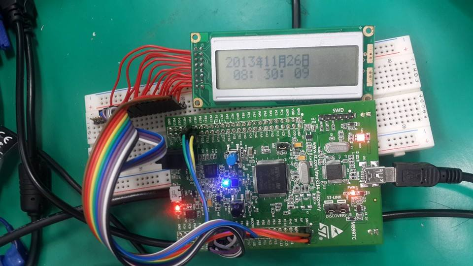
利用LCD來做RTC的應用, 可以實現時間和日期的顯示
.. code-block:: c
Previous
=============
git clone https://github.com/fboris/stm32_RTC_demo.git
cd stm32_RTC_demo
make
make flash
Generate 1Hz
LCD Introduction
===================
LCD(Liquid Crystal Display)為液晶顯示器,功耗極低,常在控制周邊時,用來顯示數據的變化。裡面已經有內建文字圖形(只有英文字母大小寫、阿拉伯數字、標點符號),只要輸入**ASCII碼**,便會將該字的圖形顯示於LCD,如果要顯示中文字可以利用CGRAM,自己做出想要的字。
我們的LCD則是用來顯示RTC的時間與日期,而下面有個簡單介紹,顯示0到9字的程式碼。
Pin Connection
--------------------
http://wiki.csie.ncku.edu.tw/embedded/RTC
RTC基本計算單位為一秒鐘。
由於clock source速度太快,我們需要用prescaler去轉換成一秒鐘。
.. image:: /stm32 RTC prescaler.png
規格參考 :http://www.sdec.com.tw/products.php?no=50
基於省電需求,將prescaler分為兩個區塊,首先經由較省電的Asynchronous prescaler,再透過較耗能量的Synchronous prescaler輸出1Hz。
根據clock source的頻率不同,我們調整不同的prescaler參數。
LCD使用了 **14 pin** .
.. image:: /embedded/RTC/ck_spre_formula.png
LSE: 32.768kHz / (127+1) / (255+1) = 1Hz
- LCD pin 1 = ground
LSI: 32kHz / (127+1) /(249+1) =1Hz
- LCD pin 2 = V+
- LCD pin 3 = ground (or use variable resistor)
- LCD pin 4 ~ 13 connection :
Previous Functionality
-------------------------
- RS = PD.08 (PIN 8 of GPIOD)
- R/W = PD.09
- E = PD.10
- DB0 = PD.00
- DB1 = PD.01
Prescaler
----------
Prescaler generates the clock to update the calendar.
- DB2 = PD.02
To minimize power comsuption the prescaler is split into two prescalers, asynchronous and synchronous. It is recommended to configure the asynchronous prescaler to a high value to minimize consumption.
- DB3 = PD.03
asynchronous prescaler clocks subsecond of calendar and propagates to synchronous prescaler to update date and time by second.
- DB4 = PD.04
One can configure them through ``PREDIV_A`` and ``PREDIV_S`` bits in ``RTC_PRER``
- DB5 = PD.05
- DB6 = PD.06
Calendar and Alarm
--------------------
A calendar keeps track of the date (day, week, month, year) and time (hours, minutes and seconds) and even subseconds. It manages of numbers of days of mouths automaticly. Daylight saving time adjustment is programmable by software.
- DB7 = PD.07
Binary repersentation is in binary-coded decimal (BCD) format.
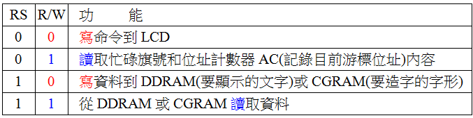
Control Method
------------------
Data can be read indirectly from shadow registers or directly from counters. The former method delays some clocks but ensures consistency between date and time registers; the later is opposite but this is especially useful after exiting from low power modes, since the shadow registers are not updated during these modes.
Data, time, and subsecond are separately recorded in ``RTC_DR``, ``RTC_TR``, and ``RTC_SSR``. With ``BYPSHAD`` bit set, data can be read directly from counter.
Two programmable alarms (Alarm A, Alarm B) with **interrupt function**. The alarms can be triggered by any **combination** of the calendar fields.
An alarm consists of a register with the same length as the RTC time counter. When the RTC time counter reaches the value programmed in the alarm register, a flag is set to indicate that an alarm event occurred.
Initial LCD Code
-------------------------
In addition to the time to trigger, alarm can be configured to mask some fields and do not compare.
.. code-block:: prettyprint
/* Initialization can decide whether to open a cursor, blink and display or not. */
void Init_LCD()
{
vTaskDelay(100);
LCD_CMD(0x003f);
vTaskDelay(10);
LCD_CMD(0x000c);
vTaskDelay(10);
LCD_CMD(0x0001);
vTaskDelay(10);
}
Auto periodic wakeup
------------------------------
A periodic timebase and wakeup unit that can wake up the system from low power modes. When this counter reaches zero, a flag and an interrupt are generated.
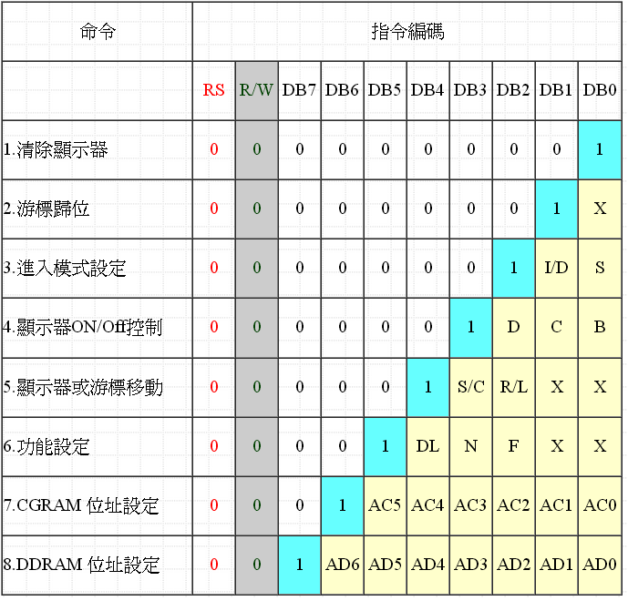
Command Register Code
-------------------------
It's source clock can be RTC clock or prescaler. Time range can be configured through ``WUCKSEL``
.. code-block:: prettyprint
/* Write command register function */
void LCD_CMD(uint16_t cmd)
{
int i;
GPIO_SetBits(LCD_DBPORT, cmd);
RS_0;
RW_0;
E_1;
vTaskDelay(1);
E_0;
GPIO_ResetBits(LCD_DBPORT, cmd);
}
Timestamp
----------
The calendar is saved in timestamp registers when timestamp event is detected on the pin which timestamp alternate function is mapped.
Data Register Code
-------------------------
.. code-block:: prettyprint
Tamper detection
--------------------
It can be used for edge detection or level detection with filtering according to ``TAMPFLT``. Set to 00 is edge detection, others arg level detection.
/* Write data register function */
void LCD_DATA(uint16_t data1)
{
int i;
GPIO_SetBits(LCD_DBPORT, data1);
RS_1;
RW_0;
E_1;
vTaskDelay(1);
E_0;
GPIO_ResetBits(LCD_DBPORT, data1);
}
When ``TAMPTS`` set to 1, tamper event trigger timestamp event automatically.
Display String
-------------------------
.. code-block:: prettyprint
Backup registers
--------------------
Program can read or write data from or to these registers, which are not reset by system reset or power-on reset. They are reset when tamper detection event occurs.
/* Testing LCD can display 0~9 */
void LCD_display(char row,char column, char display[])
{
char *str;
uint16_t address;
str=display;
address=0x0080+0x0040*(row-1)+(column-1);
LCD_CMD(address);
vTaskDelay(10);
while(*str!=0){
LCD_DATA(*str++);
vTaskDelay(5);
}
str=display;
}
------------------------------------
Alternate function outputs
------------------------------
Two outputs are avalible : ``RTC_CALIB`` and ``RTC_ALARM``.
Q & A
================
``RTC_CALIB`` output is used to generate a variable-frequency signal. It can use either asynchronous or synchronous prescaler as clock.
**1.潤年是否可調整?**
besides alarm, ``RTC_ALARM`` can use wakeup timer as source.
Ans:
可以, RTC提供了自動調整潤年的功能。
Synchronization and Reference clock detection
--------------------------------------------------
RTC can be synchronized to remote clock by adding a 'shift' to counter continuously to delay, or vice versa.
With reference clock detection, RTC shifts misaligned 1 Hz clock to align it with the nearst referenced edge (found in a given time window).
參考手冊 p.536.( Compensations for 28-, 29- (leap year), 30-, and 31-day months are performed automatically.)
One can adjust time by configuring shift through ``RTC_SHIFTR``.
-----------------------------------------------------------------------------------------------------------------
When reference clock detection is enabled (``REFCKON``), must not write ``RTC_SHIFTR`` and not enable calibration and set prescalers (``PREDIV_A`` and ``PREDIV_S``) to default.
**2.為什麼要存在shadow register?**
Ans:
Digital calibration
--------------------
Calibration can be used to compensate inaccuracy of oscillator by adding or substracting clock cycles in each calibration cycle.
- 有些暫存器是兩層的,第一層是給CPU存取,第二層是給硬體存取,像是我們使用的**shadow register **與**硬體**其實它們兩個就是上下層的關係,不過是屬於同一個暫存器(**calendar register**)。CPU在寫入暫存器時,會先寫入在上層的shadow register,隨後硬體更新之後才會在下層動作, 所以shadow register 可以直接對硬體存取 。
There are two calibration methods : coarse and smooth. They should not be used togather. The cycle of the later is smaller than the former. It makes the later is more flexible to adjust clock. A smooth calibration can be performed on the fly so that it can be changed to handle changed envirenment variables.
- 而當我們讀取calendar register時, APB1的clock頻率必須等於或大於RTC的clock頻率才行, **存在shadow register是為了可以確保同步機制的安全**, 如果APB1 clock頻率小於RTC clock頻率的話,CPU可能會讀到兩次的時間與日期。所以在初始化時,必須採用shadow register,才不會造成同步上的問題。
coarse calibration is provided for capability reasons. It can only be configured in initialization mode and start when INIT bit is cleared. Also it is recommaned using it for static correction only.
參考手冊 p.539
--------------------------------------
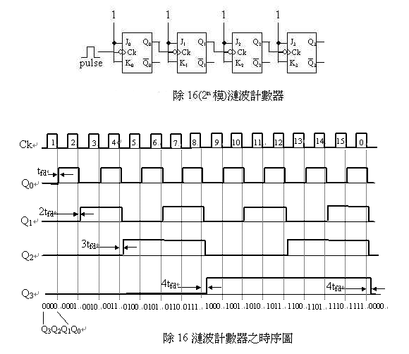
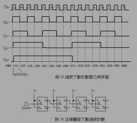
**3.下數(down counter)如何實現?**
Ans:
- 計數器由正反器構成,可以記錄狀態的變遷,或可說是正反器隨時脈的變化次數做故定狀態的循環。
- 要變成**下數計時器**只要在負緣觸發改成正緣觸發即可, 等於**時脈輸入端加了反閘**。
Previous Configuration Register write protection
-------------------------------------------------------
After system **reset**, the RTC registers are protected registers are automatically locked to against **possible parasitic write accesses**.
-------------------------------------------------------------------------
RTC registers need to **disable** backup domain protection to update the current calendar time and date.
補充:
set ``DBP`` bit in ``PWR_CR``
**上數計時器**
After power-up reset, the RTC registers are also protected and need to write a key into protection register. RTC_ISR[13:8], RTC_TAFCR, and RTC_BKPxR are except. Write a wrong key will enable protection.
write ``0xCA`` to ``RTC_WPR``
**下數計時器**
write ``0x53`` to ``RTC_WPR``
Initialization mode
--------------------
Modifications of ``RTC_DR``, ``RTC_TR``, and ``RTC_PRER`` must be done in Initialization mode.
----------------------------------------------
**4.Backup domain 為什麼從1.65V轉成1.2V?**
set ``INIT`` bit of ``RTC_ISR`` to enter Initialization mode
Ans:
wait until ``RTC_ISR`` / ``INITF`` is set then ready to write
因一般電池的電壓為1.5~1.2V, 而Backup domain只需在1.2V以上即可工作。
reset ``INIT`` bit of ``RTC_ISR`` to exit Initialization mode
ps. 一般電池的電壓為1.5v(鹼性電池)至1.2(一般及充電電池)
Counter does not run in Initialization mode.
而有關於1.65v的部份應該是跟debugger的界面有關係,st的st-link供應的電壓為1.65v至5v,相似的設計在ti的msp 430 usb debugger
也可以看到類似的設計(1.8v~3.6v)
ST-LINK:http://www.st.com/web/catalog/tools/FM146/CL1984/SC724/SS1677/PF251168
MSP430 USB Debugging Interface :http://www.ti.com/tool/cc-debugger
--------------------------------------------------------------------------------------
Reference
================
`RTC application note<http://www.st.com/st-web-ui/static/active/cn/resource/technical/document/application_note/DM00025071.pdf>`_
[RTC application note](http://www.st.com/st-web-ui/static/active/cn/resource/technical/document/application_note/DM00025071.pdf)
`STM32F405xx/07xx, STM32F415xx/17xx, STM32F42xxx and STM32F43xxx Reference Manual
<http://www.st.com/st-web-ui/static/active/en/resource/technical/document/reference_manual/DM00031020.pdf>`_
`共筆<https://hackpad.com/STM32F74-RTCReal-Time-Clock-eclVxLGTj50>`_
`STM32F407 Datasheet
<http://www.st.com/st-web-ui/static/active/en/resource/technical/document/datasheet/DM00037051.pdf>`_
[LCD introduction (選左邊清單的"LCD控制")](http://faculty.stust.edu.tw/~wjshieh/)
[電池規格](http://zh.wikipedia.org/wiki/%E4%B9%BE%E9%9B%BB%E6%B1%A0/)
