版本 642383b3b702954e5f3a46beb8d894dd11086fe3
I2C: Inter-Integrated Circuit
I²C 簡介
I²C(Inter-Integrated Circuit)是內部整合電路的稱呼,是一種串列通訊匯流排,由Philips公司在1980年代為了讓主機板、手機及嵌入式系統用以連接低速周邊裝置而發展,主要應用在board-to-board,它的設計並不能應用到長距離裝置的通訊。不過,I2C bus 可以被應用在各種控制架構上,如系統管理匯流排(System Management Bus, SMBus)、電源管理匯流排(Power Management Bus, PMBus)、智慧平台管理介面(Intelligent Platform Management Interface, IPMI)、顯示數據通道(Display Data Channel, DDC)、先進電信運算架構(Advanced Telecom Computing Architecture, ATCA)。
I²C的參考設計使用一個7位元長度的位址空間但保留了16個位址,所以在一組匯流排最多可和112個節點通訊。常見的I²C匯流排依傳輸速率的不同而有不同的模式:標準模式(100 Kbit/s)、低速模式(10 Kbit/s),但時脈頻率可被允許下降至零,這代表可以暫停通訊。而新一代的I²C匯流排可以和更多的節點(支援10位元長度的位址空間)以更快的速率通訊:快速模式(400 Kbit/s)、高速模式(3.4 Mbit/s)。
I²C bus
I2C 使用兩條雙向 open-drain Line:
SDA : Serial Data Line, holds Data or address signal
SCL : Serial Clock Line, holds Clock signal
導通時是低電位,不導通時float,所以利用電阻(pullup resistor)將電位拉高。常用電壓為 +5 V or +3.3 V。
IO 必須是 open drain (or open collector in TTL)
bus 為 wired-AND configuration
SDA must be stable when SCL is high, excluding Start/Stop condition
pullup resistor :
- 要根據bus總電容及rising time來選用pullup resistor的大小 (ref)
Definition of I2C-bus terminology :
- Transmitter : the device which sends data to the bus
- Receiver : the device which receives data from the bus
- Master : the device which initiates a transfer, generates clock signals and terminates a transfer
- Slave : the device addressed by a master
- Multi-master : more than one master can attempt to control the bus at the same time without corrupting the message
- Arbitration : procedure to ensure that, if more than one master simultaneously tries to control the bus, only one is allowed to do so and the winning message is not corrupted
- Synchronization : procedure to synchronize the clock signals of two or more devices.
Master & Slave mode :
- Master node — node that generates the clock and initiates communication with slaves
- Slave node — node that receives the clock and responds when addressed by the master
- Each device connected to the bus is software addressable by a unique address and simple master/slave relationships exist at all times; masters can operate as master-transmitters or as master-receivers.
- It is a true multi-master bus including collision detection and arbitration to prevent data corruption if two or more masters simultaneously initiate data transfer.
- Serial, 8-bit oriented, bidirectional data transfers can be made at up to 100 kbit/s in the Standard-mode, up to 400 kbit/s in the Fast-mode, up to 1 Mbit/s in Fast-mode Plus, or up to 3.4 Mbit/s in the High-speed mode.
I²C data mode :
- master transmit — master node is sending data to a slave
- master receive — master node is receiving data from a slave
- slave transmit — slave node is sending data to the master
- slave receive — slave node is receiving data from the master
![]()
I²C data Transmit :
- Data Transfer is initiated with a START bit (S) signaled by SDA being pulled low while SCL stays high.
- SDA sets the 1st data bit level while keeping SCL low (during blue bar time.)
- The data is sampled (received) when SCL rises (green) for the first bit (B1).
- This process repeats, SDA transitioning while SCL is low, and the data being read while SCL is high (B2, Bn).
- A STOP bit (P) is signaled when SDA is pulled high while SCL is high.
I²C arbitration
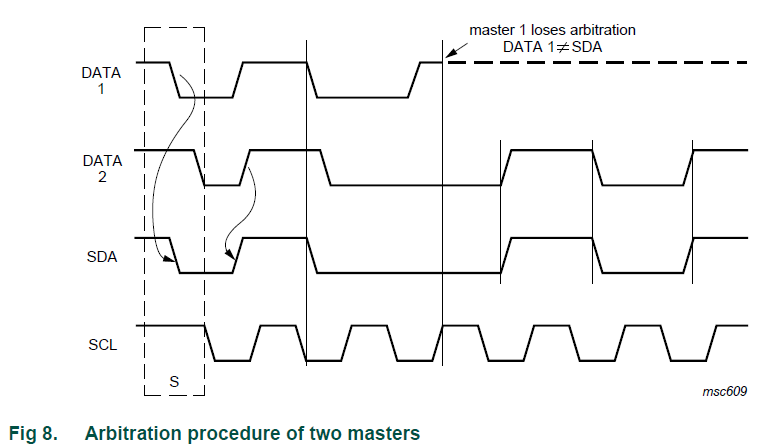
I²C 的仲裁
- 避免同時間有 2個以上的master (不同資料) 控制 i2c
- 利用 bus wired-AND 的機制,若 Master 1 欲將 SDA logic 拉高,最後卻 SDA logic 為低,代表仲裁輸了,該 master 立即停止動作。
- 輸掉的 master 寧可先放棄 (Back Off) 等候,到看見停止狀態的出現才開始傳送。
I²C Speed
一開始的I2C bus 操作的速度被限制在100kbit/s,不過隨著時代的演進,新增了一些模式,所以現在的規範分成五種操作速度:
- 雙向
- 標準模式 (Standard-mode), 速率可高達 100 kbit/s
- 快速模式 (Fast-mode), 速率可高達 400 kbit/s
- 快速模式PLUS (Fast-mode Plus), 速率可高達 1 Mbit/s
- 高速模式 (High-speed mode), 速率可高達 3.4 Mbit/s.
- 單向
- 超快速模式(Ultra Fast-mode), 速率可高達 5 Mbit/s
快速模式的設備可以在400kbit/s 下做接收和傳送。並且向下相容,可以和標準模式的設備在0~100kbit/s 的I2C bus 通訊。快速模式與標準模式的比較如下:
- 最大速率增加到400kbit/s
- 調整 序列資料SDA 和 序列時脈SCL的時序
- 快速模式設備的輸入有 spike suppression的功能,SDA和SCL的輸入有Schmitt trigger
- 快速模式設備的輸出Buffer 對SDA和SCL信號的下降緣有斜率控制功能
- 如果快速模式設備的電源電壓被關閉,SDA和SCL的I/O pin 必須浮接,才不會阻塞BUS
I²C與I²S的差異
I²C(Inter-Integrated Circuit ) 與 I²S當初同樣是為進行音頻資料的串列通訊協議,但就功能面的支援還是有差異, I²C提供多個主控端串接多個從屬裝置其同步與資料透過雙線式雙向同步傳遞,其傳輸速率分為有100khz,400khz and 3.5mhz 由於這些時脈都是處理較普遍的裝置,I²S提供三線式主控端單向多從屬裝置, 其傳輸速率分為 2.5MHz.
I²S (inter-integrated sound) : STM32F429 Discovery 提供兩組 I²S介面(由內部的多工器切換 SPI2 及 SPI3這兩組) ,[1] pp.37 ; 所以基本上一個時脈以400ns計算, 其傳輸頻率為2.5MHz,將足夠提供24bits之48khz取樣的雙聲道音源, 主要是支援MPGE2,4等; 而44.1kKHz 取樣頻率則是支援MP3格式 : 24bits x 48000Hz x 2channel = 2304000bits/Sec = 2.304Mbps
STM32F429 Discovery I2S and SPI 的腳位定義 (LQFP 144 PIN) pin 96 , I2S2_MCK | pin 74 , I2S2_CK/SPI2_SC | pin 76 , I2S2_SD/ SPI2_MOS
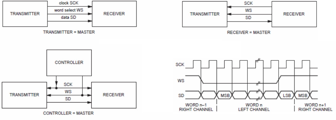
傳輸匯流排I²C 為 SCK (Continuous serial clock)與 SD 兩條, 如果是採用Board to Cable 建議加上一條GND 。
在I²S匯流排通道上只有一個傳輸控制器與一個主控端(Master)角色的監控裝置,該匯流排共有三條傳輸線分別為,同步時脈 SCK (Continuous serial clock) , 字串選擇的WS (Select dates) 以及進行資料傳輸的 SD(serial data ) 三條傳輸線, 並含GND共地線。
I²S的角色可以是一個主控端(Master)監控裝置,也可以同時是一個傳輸控制器(Tx), 接收器(Rx) 或是兩個從端角色的裝置。
I²S 介面傳輸資料具有兩個左右音訊通道的資料, 它靠 WS = 0 設定為零時; 定義為 通道 1 (左聲道資料讀取) ; WS = 1 ; 通道 2 (右聲道資料讀取)。
I²C 特性
I²C 串列傳輸包括四個部分:起始信號、設備位址發送、數據傳送和停止信號。
- 只能Master<->Slave,無法Slave<->Slave,每個slave都要有一個特定且唯一的位址。
- START condition: SCL=High 且 SDA為負緣
- STOP condition: SCL=High 且 SDA=為正緣
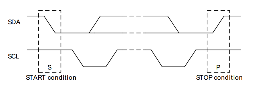
由Master發送起始信號來開啟通訊,所有的slave device接收到起始信號後會進入接收數據模式。接著Master需要發送通訊目標設備的address及R/W資訊。
- STM32F429提供兩種 address mode - 7bit and 10bit
- 7bit mode: 發送 7bit 的address (MSB) 及一位元的 R(1)/W(0)後,該 address 的slave端會發送一個bit的 Ack(acknowledge) bit,ACK=0表設定成功(Slave把SDA拉到LOW),開始數據傳送。
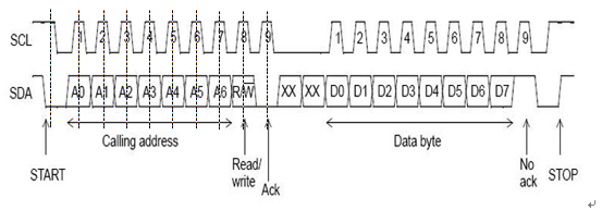
7bit mode - 10bit mode: 總共用兩個byte來傳送 address資訊。第一個byte的前五個位元需為 "11110" 來表示要使用 10-bit addressing。
10bit mode - STM32F429提供兩種 address mode - 7bit and 10bit
資料傳輸
- 在 SCL 為 HIGH 時,SDA 必須是 stable 的。
- SDA 只能在 SCL 為 LOW 時改變。
- 一次傳一個 byte,每個byte都跟著一個 ACK bit ,在 ACK bit 時 Master 會釋放bus,此時 Slave 端需把 SDA 拉 LOW,否則 Master 需要發出 STOP訊號 或是重新發送 START 訊號。
- 在每個 byte 之間 Slave 端可以把 SCL 拉 LOW 來強制讓傳輸暫停。
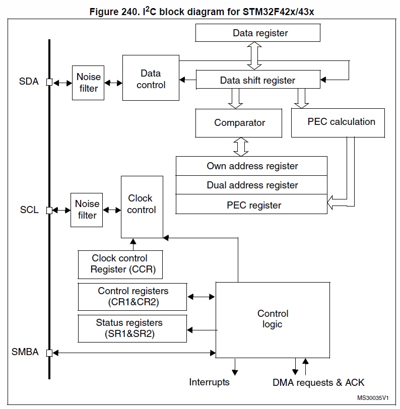
I²C functional description
I²C block diagram(on STM32F42x)
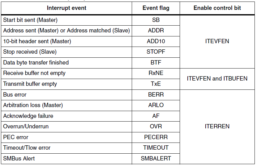
I²C interrupt and Event
2 Interrupt vectors - successful address/ data communication (ITEVFEN ITBUFEN) - error condition (ITERREN)
Registers
clock control register
設定I2C CCR:
- Sm mode 的 peripheral input clock 至少要為 2MHz。
- Fm mode 的頻率 peripheral input clock 至少要為 4MHz。
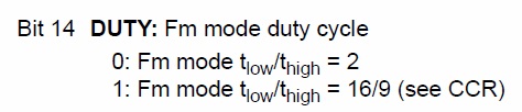
設定 Fm mode 的duty cycle
透過設定CCR來產生SCL頻率。
例如: 當在Sm mode時,若 FREQR為08 (8MHz), TPCLK1為 125ns, 則CCR必須要是0x28(40d × 125ns × 2 = 10000ns), 才能產生100KHz的SCL
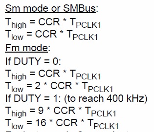
control register
ACK: Acknowledge enable
STOP: Stop generation
START: Start generation
NOSTRETCH: Clock stretching disable (Slave mode)
當STOP, START bit 被set後, 在他們被硬體clear前不能從軟體寫入I2C_CR1。
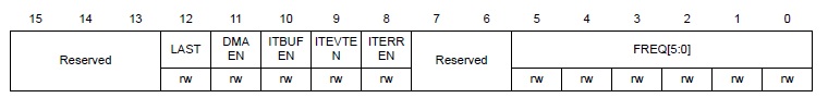
ITBUFEN: Buffer interrupt enable
1: TxE = 1 or RxNE = 1 generates Event Interrupt
ITEVTEN: Event interrupt enable
1: Event interrupt enabled 當下列status register 被set 時會觸發中斷。
- SB = 1 (Master)
- ADDR = 1 (Master/Slave)
- ADD10= 1 (Master)
- STOPF = 1 (Slave)
- BTF = 1 with no TxE or RxNE event
- TxE event to 1 if ITBUFEN = 1
- RxNE event to 1 if ITBUFEN = 1
ITERREN: Error interrupt enable
1: Error interrupt enabled 當下列status register 被set 時會觸發中斷。
- BERR = 1
- ARLO = 1
- AF = 1
- OVR = 1
- PECERR = 1
- TIMEOUT = 1
- SMBALERT = 1
status register
.png)
.png)
/**
 * @brief  SR1 register flags
 */
#define I2C_FLAG_SMBALERT        //SMBus alert
#define I2C_FLAG_TIMEOUT         //Timeout or Tlow error
#define I2C_FLAG_PECERR          //PEC Error in reception
#define I2C_FLAG_OVR             //Overrun/Underrun
#define I2C_FLAG_AF              //Acknowledge failure
#define I2C_FLAG_ARLO            //Arbitration lost (master mode)
#define I2C_FLAG_BERR            //Bus error 傳輸時,在SCL為HIGH時,SDA產生 rising or falling edge
#define I2C_FLAG_TXE             //Data register empty (transmitters)
#define I2C_FLAG_RXNE            //RxNE: Data register not empty (receivers)
#define I2C_FLAG_STOPF           //Stop detection (slave mode)
#define I2C_FLAG_ADD10           //10-bit header sent (Master mode)
#define I2C_FLAG_BTF             //Byte transfer finished
#define I2C_FLAG_ADDR            //Address sent (master mode)/matched (slave mode)
#define I2C_FLAG_SB              //Start bit (Master mode)

/**
* @brief  SR2 register flags
*/
#define I2C_FLAG_DUALF           //Dual flag (Slave mode)
#define I2C_FLAG_SMBHOST         //SMBus host header (Slave mode)
#define I2C_FLAG_SMBDEFAULT      //SMBus device default address (Slave mode)
#define I2C_FLAG_GENCALL         //General call address (Slave mode)
#define I2C_FLAG_TRA             //Transmitter/receiver
#define I2C_FLAG_BUSY            //Bus busy
#define I2C_FLAG_MSL             //Master/slave
(暫存器可參考 http://www.eng.auburn.edu/~nelson/courses/elec5260_6260/STM32F4%20I2C.pdf)
I2C bus “events” from flags
I2C Master Events
/* --EV5--- BUSY, MSL and SB flag */
#define  I2C_EVENT_MASTER_MODE_SELECT                 ((uint32_t)0x00030001)
/* --EV6--- BUSY, MSL, ADDR, TXE and TRA flags */
#define  I2C_EVENT_MASTER_TRANSMITTER_MODE_SELECTED   ((uint32_t)0x00070082)
/* BUSY, MSL and ADDR flags */
#define  I2C_EVENT_MASTER_RECEIVER_MODE_SELECTED      ((uint32_t)0x00030002)
/* --EV9--- BUSY, MSL and ADD10 flags */
#define  I2C_EVENT_MASTER_MODE_ADDRESS10              ((uint32_t)0x00030008)

/* Master RECEIVER mode -----------------------------*/
/* --EV7--- BUSY, MSL and RXNE flags */
#define  I2C_EVENT_MASTER_BYTE_RECEIVED               ((uint32_t)0x00030040)

/* Master TRANSMITTER mode --------------------------*/
/* --EV8--- TRA, BUSY, MSL, TXE flags */
#define I2C_EVENT_MASTER_BYTE_TRANSMITTING            ((uint32_t)0x00070080)
/* --EV8_2--- TRA, BUSY, MSL, TXE and BTF flags */
#define  I2C_EVENT_MASTER_BYTE_TRANSMITTED            ((uint32_t)0x00070084)
I2C Slave Events
/* --EV1--- BUSY and ADDR flags */
#define  I2C_EVENT_SLAVE_RECEIVER_ADDRESS_MATCHED          ((uint32_t)0x00020002)
/* TRA, BUSY, TXE and ADDR flags */
#define  I2C_EVENT_SLAVE_TRANSMITTER_ADDRESS_MATCHED       ((uint32_t)0x00060082)
/* Slave RECEIVER mode --------------------------*/
/* --EV2--- BUSY and RXNE flags */
#define  I2C_EVENT_SLAVE_BYTE_RECEIVED                     ((uint32_t)0x00020040)
/* --EV4--- STOPF flag  */
#define  I2C_EVENT_SLAVE_STOP_DETECTED                     ((uint32_t)0x00000010)

/* Slave TRANSMITTER mode -----------------------*/
/* --EV3--- TRA, BUSY, TXE and BTF flags */
#define  I2C_EVENT_SLAVE_BYTE_TRANSMITTED                  ((uint32_t)0x00060084)
/* TRA, BUSY and TXE flags */
#define  I2C_EVENT_SLAVE_BYTE_TRANSMITTING                 ((uint32_t)0x00060080)
/* --EV3_2-- AF flag */
#define  I2C_EVENT_SLAVE_ACK_FAILURE                       ((uint32_t)0x00000400)
four I²C modes
有兩種實作方法,一種是使用While(!I2C_CheckEvent())來等待 Event,或是使用中斷並透過IRQ_Handler來做相應的處理。
以下以7 bit address mode 作範例
Master transmitter
![]()
WriteOneByte
- 產生 start bit: I2C_GenerateSTART()
- 等待EV5: while(!I2C_CheckEvent(I2Cx, I2C_EVENT_MASTER_MODE_SELECT));
- 傳送7bit address與傳輸模式: I2C_Send7bitAddress(i2cx, i2c_ADDR, I2C_Direction_Transmitter);
- 等待EV6: while(!I2C_CheckEvent(I2Cx, I2C_EVENT_MASTER_TRANSMITTER_MODE_SELECTED));
- 傳送一個byte: I2C_SendData(I2Cx);
- 確認BYTE傳送完成: while( !I2C_CheckEvent(I2Cx, I2C_EVENT_MASTER_BYTE_TRANSMITTER) );
- 產生 stop bit: I2C_GenerateSTOP();
Master receiver
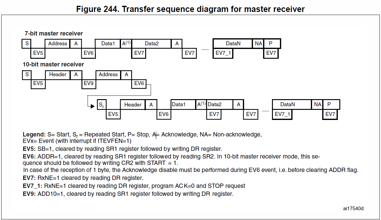
ReadOneByte
- 產生 start bit: I2C_GenerateSTART()
- 等待EV5: while(!I2C_CheckEvent(I2Cx, I2C_EVENT_MASTER_MODE_SELECT));
- 傳送7bit address與傳輸模式: I2C_Send7bitAddress(i2cx, i2c_ADDR, I2C_Direction_Receiver);
- 等待EV6: while(!I2C_CheckEvent(I2Cx, I2C_EVENT_MASTER_RECEIVER_MODE_SELECTED));
- 確認BYTE接收完成: while( !I2C_CheckEvent(I2Cx, I2C_EVENT_MASTER_BYTE_RECEIVED) );
- 讀取DR暫存器: I2C_ReceiveData(I2Cx);
- 產生 stop bit: I2C_GenerateSTOP();
Slave transmitter
![]()
- 等待EV1
- 中斷 -> I2C_EVENT_SLAVE_TRANSMITTER_ADDRESS_MATCHED
- 等待EV2
- 中斷-> I2C_EVENT_SLAVE_BYTE_TRANSMITTED (TxE=1) -> I2C_SendData() (WRITE DR register)
- 等待EV4
- 中斷->I2C_EVENT_SLAVE_STOP_DETECTED(STOPF=1) -> 結束
Slave receiver
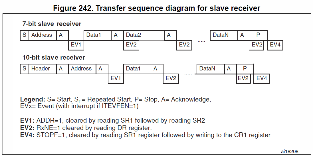
- 等待EV1
- 中斷 -> I2C_EVENT_SLAVE_RECEIVER_ADDRESS_MATCHED
- 等待EV3 (EV3_1)
- 中斷-> I2C_EVENT_SLAVE_BYTE_RECEIVED (RxNE=1) -> I2C_ReceiveData() (READ DR register)
- 等待EV3_2
- 中斷->NACK -> 結束 (Master接到NACK後產生stop condition)
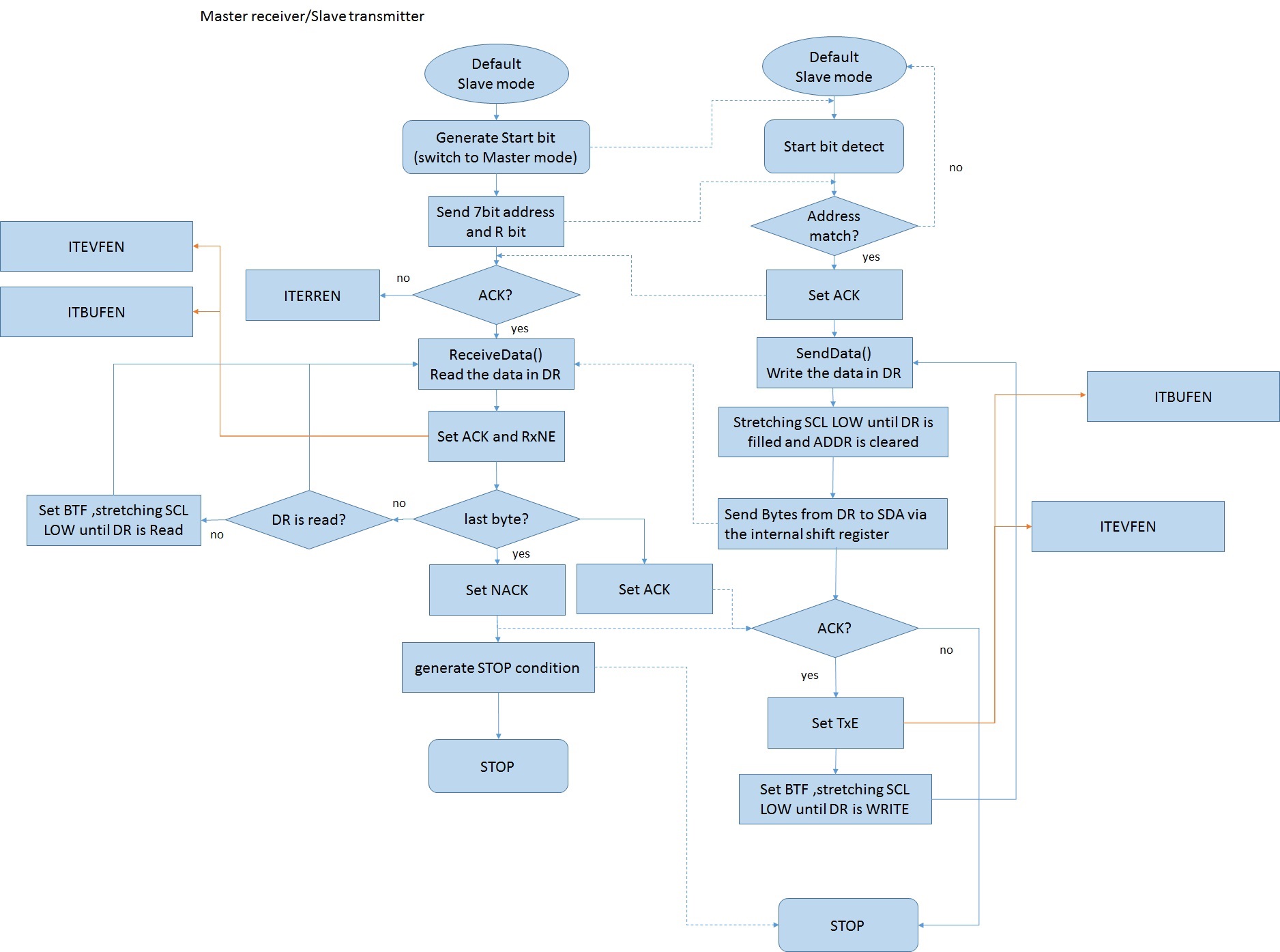
flow chart(two boards)
- master transmitter/slave receiver
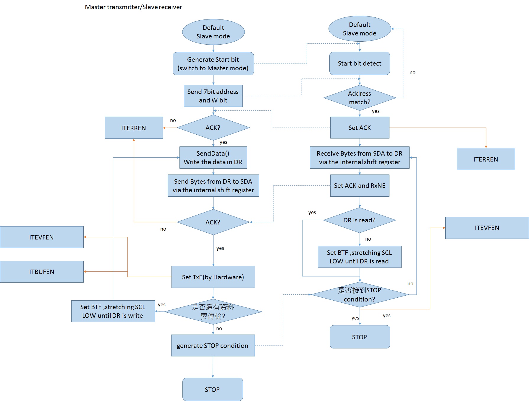
- master receiver/slave transmitter
I²C on STM32F429-Discovery
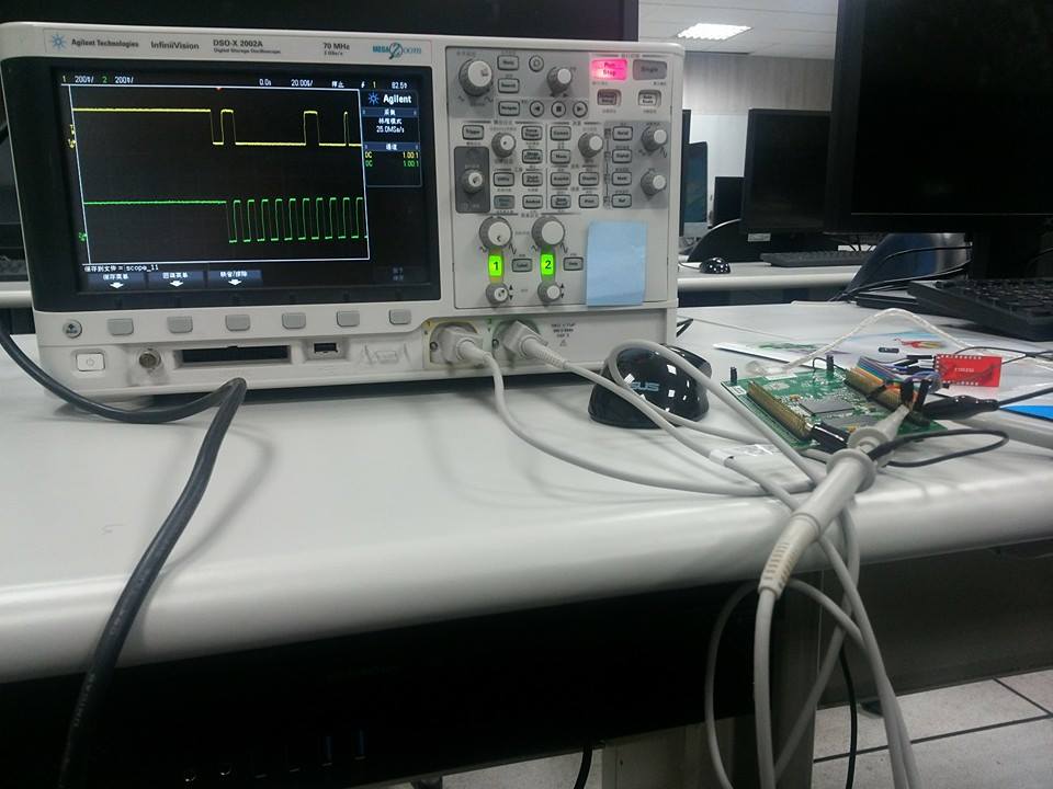
實驗一: touch panel
觀察及使用觸控螢幕,並量測對應的i2c訊號
demo code:
git clone https://github.com/colin8930/stm32_touchpanel_i2c.git
cd stm32_touchpanel_i2c
make
make flashstm32f429i_discovery_ioe.h:
#define IOE_I2C                    I2C3
#define IOE_I2C_CLK                RCC_APB1Periph_I2C3
#define IOE_I2C_SCL_PIN            GPIO_Pin_8
#define IOE_I2C_SCL_GPIO_PORT      GPIOA
#define IOE_I2C_SCL_GPIO_CLK       RCC_AHB1Periph_GPIOA
#define IOE_I2C_SCL_SOURCE         GPIO_PinSource8
#define IOE_I2C_SCL_AF             GPIO_AF_I2C3
#define IOE_I2C_SDA_PIN            GPIO_Pin_9
#define IOE_I2C_SDA_GPIO_PORT      GPIOC
#define IOE_I2C_SDA_GPIO_CLK       RCC_AHB1Periph_GPIOC
#define IOE_I2C_SDA_SOURCE         GPIO_PinSource9
#define IOE_I2C_SDA_AF             GPIO_AF_I2C3
#define IOE_I2C_DR ((uint32_t)0x40005C10)stm32f429i_discovery_ioe.c:
GPIO 設定
GPIO_InitTypeDef GPIO_InitStructure;

/* 設定RCC clock*/
/* Enable IOE_I2C and IOE_I2C_GPIO_PORT & Alternate Function clocks */
RCC_APB1PeriphClockCmd(IOE_I2C_CLK, ENABLE);
RCC_AHB1PeriphClockCmd(IOE_I2C_SCL_GPIO_CLK | IOE_I2C_SDA_GPIO_CLK |
                     IOE_IT_GPIO_CLK, ENABLE);
RCC_APB2PeriphClockCmd(RCC_APB2Periph_SYSCFG, ENABLE);

/* Reset IOE_I2C IP */
RCC_APB1PeriphResetCmd(IOE_I2C_CLK, ENABLE);
/* Release reset signal of IOE_I2C IP */
RCC_APB1PeriphResetCmd(IOE_I2C_CLK, DISABLE);

/*設定PA8、PC9 的Alternate function設為 GPIO_AF_I2C3*/
/* Connect PXx to I2C_SCL*/
GPIO_PinAFConfig(IOE_I2C_SCL_GPIO_PORT, IOE_I2C_SCL_SOURCE, IOE_I2C_SCL_AF);
/* Connect PXx to I2C_SDA*/
GPIO_PinAFConfig(IOE_I2C_SDA_GPIO_PORT, IOE_I2C_SDA_SOURCE, IOE_I2C_SDA_AF);

/* 設定 SCL、SDA pin*/
/* IOE_I2C SCL and SDA pins configuration */
GPIO_InitStructure.GPIO_Pin = IOE_I2C_SCL_PIN;
GPIO_InitStructure.GPIO_Mode = GPIO_Mode_AF;
GPIO_InitStructure.GPIO_Speed = GPIO_Speed_50MHz;
GPIO_InitStructure.GPIO_OType = GPIO_OType_OD;
GPIO_InitStructure.GPIO_PuPd  = GPIO_PuPd_NOPULL;
GPIO_Init(IOE_I2C_SCL_GPIO_PORT, &GPIO_InitStructure);

GPIO_InitStructure.GPIO_Pin = IOE_I2C_SDA_PIN;
GPIO_Init(IOE_I2C_SDA_GPIO_PORT, &GPIO_InitStructure);
I2C參數設定
I2C_InitTypeDef I2C_InitStructure;

/* If the I2C peripheral is already enabled, don't reconfigure it */
if ((IOE_I2C->CR1 & I2C_CR1_PE) == 0) {
    /* 設定 I2C參數*/
    /* IOE_I2C configuration */
    I2C_InitStructure.I2C_Mode = I2C_Mode_I2C;
    I2C_InitStructure.I2C_DutyCycle = I2C_DutyCycle_2;
    I2C_InitStructure.I2C_OwnAddress1 = 0x00;
    I2C_InitStructure.I2C_Ack = I2C_Ack_Enable;
    I2C_InitStructure.I2C_AcknowledgedAddress = I2C_AcknowledgedAddress_7bit;
    I2C_InitStructure.I2C_ClockSpeed = I2C_SPEED;

    /* Initialize the I2C peripheral */
    I2C_Init(IOE_I2C, &I2C_InitStructure);

    /* Enable the I2C peripheral */
    I2C_Cmd(IOE_I2C, ENABLE);
}
touch panel demo code 一開始會先檢查 device ID及通訊是否正確
uint16_t IOE_ReadID(void) {
    uint16_t tmp = 0;

    /* Read device ID  */
    tmp = I2C_ReadDeviceRegister(0);
    tmp = (uint32_t)(tmp << 8);
    tmp |= (uint32_t)I2C_ReadDeviceRegister(1);

    /* Return the ID */
    return (uint16_t)tmp;
}

uint8_t I2C_ReadDeviceRegister(uint8_t RegisterAddr) {
    uint8_t tmp = 0;

    /* Enable the I2C peripheral */
    I2C_GenerateSTART(IOE_I2C, ENABLE);

    /* Test on EV5 and clear it */
    IOE_TimeOut = TIMEOUT_MAX;
    while (!I2C_GetFlagStatus(IOE_I2C, I2C_FLAG_SB));

    /* Disable Acknowledgement */
    I2C_AcknowledgeConfig(IOE_I2C, DISABLE);

    /* Transmit the slave address and enable writing operation */
    I2C_Send7bitAddress(IOE_I2C, IOE_ADDR, I2C_Direction_Transmitter);

    /* Test on EV6 and clear it */
    IOE_TimeOut = TIMEOUT_MAX;
    while (!I2C_GetFlagStatus(IOE_I2C, I2C_FLAG_ADDR));

    /* Read status register 2 to clear ADDR flag */
    IOE_I2C->SR2;

    /* Test on EV8 and clear it */
    IOE_TimeOut = TIMEOUT_MAX;
    while (!I2C_GetFlagStatus(IOE_I2C, I2C_FLAG_TXE));

    /* Transmit the first address for r/w operations */
    I2C_SendData(IOE_I2C, RegisterAddr);

    /* Test on EV8 and clear it */
    IOE_TimeOut = TIMEOUT_MAX;
    while ((!I2C_GetFlagStatus(IOE_I2C, I2C_FLAG_TXE)) || (!I2C_GetFlagStatus(IOE_I2C, I2C_FLAG_BTF)));

    /* Regenerate a start condition */
    I2C_GenerateSTART(IOE_I2C, ENABLE);

    /* Test on EV5 and clear it */
    IOE_TimeOut = TIMEOUT_MAX;
    while (!I2C_GetFlagStatus(IOE_I2C, I2C_FLAG_SB));

    /* Transmit the slave address and enable writing operation */
    I2C_Send7bitAddress(IOE_I2C, IOE_ADDR, I2C_Direction_Receiver);

    /* Test on EV6 and clear it */
    IOE_TimeOut = TIMEOUT_MAX;
    while (!I2C_GetFlagStatus(IOE_I2C, I2C_FLAG_ADDR));

    /* Read status register 2 to clear ADDR flag */
    IOE_I2C->SR2;

    /* Test on EV7 and clear it */
    IOE_TimeOut = TIMEOUT_MAX;
    while (!I2C_GetFlagStatus(IOE_I2C, I2C_FLAG_RXNE));

    /* End the configuration sequence */
    I2C_GenerateSTOP(IOE_I2C, ENABLE);

    /* Load the register value */
    tmp = I2C_ReceiveData(IOE_I2C);

    /* Enable Acknowledgement */
    I2C_AcknowledgeConfig(IOE_I2C, ENABLE);

    /* Return the read value */
    return tmp;
}
(待補)
SCL: PA8
SDA: PC9
slave address: 0x82 (0x10000010) (可以在datasheet p10找到)
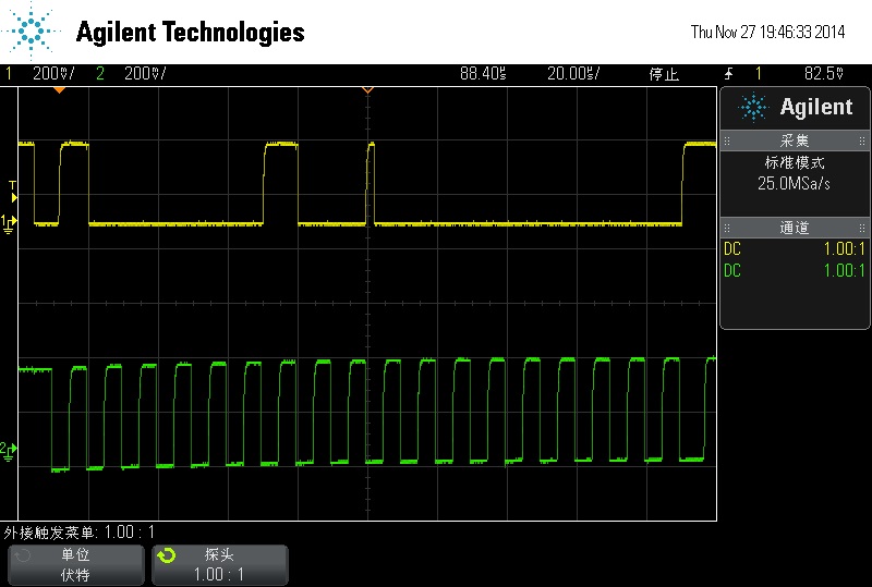 start bit -> send address and
transmitter bit -> ack -> senddata(register address 0x00)
start bit -> send address and
transmitter bit -> ack -> senddata(register address 0x00)
 start bit -> send address and
receiver bit -> ack -> data send by slave
start bit -> send address and
receiver bit -> ack -> data send by slave
 stop bit -> start bit ->
send address and transmitter bit -> ack -> senddata(register
address 0x01)
stop bit -> start bit ->
send address and transmitter bit -> ack -> senddata(register
address 0x01)
 start bit -> send address and
receiver bit -> ack -> data send by slave
start bit -> send address and
receiver bit -> ack -> data send by slave
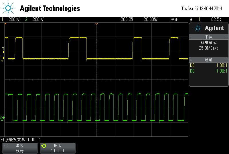
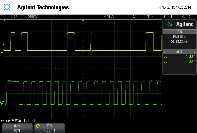
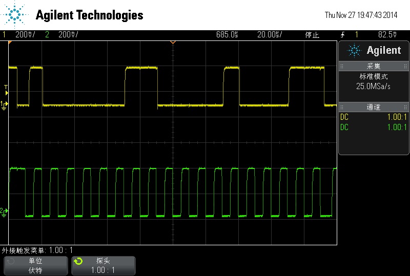
 改變I2C CLOCK SPEED ->
400kHz
改變I2C CLOCK SPEED ->
400kHz
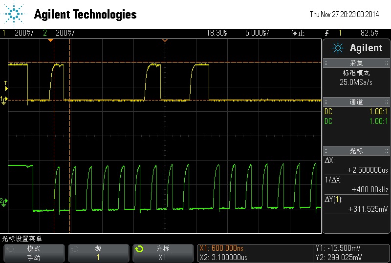
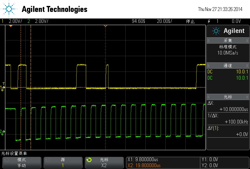 要注意探棒衰減…
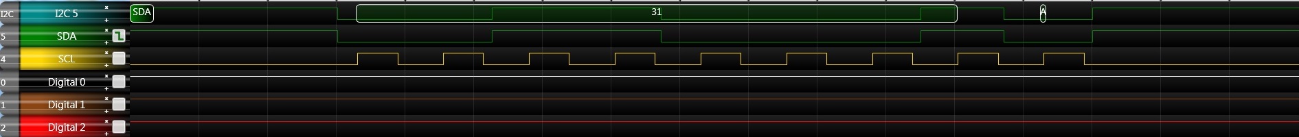
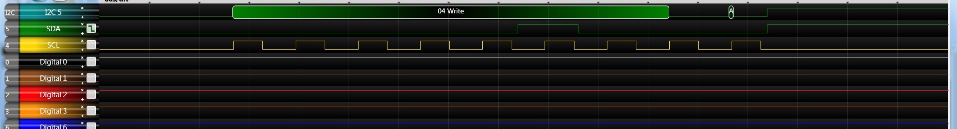
以下是邏輯分析儀的結果
 IOE_ReadID()
讀0x00、0x01暫存器的值
IOE_ReadID()
讀0x00、0x01暫存器的值
start bit -> 0x82(slave address) + W bit -> Send 0x00 -> start bit -> 0x82(slave address) + R bit ->Receive 0x08 ->
start bit -> 0x82(slave address) + W bit -> Send 0x01 -> start bit -> 0x82(slave address) + R bit ->Receive 0x11

I2C_ReadDeviceRegister(IOE_REG_TP_CTRL); //IOE_REG_TP_CTRL = 0x40. 如果panel有被觸碰,會回傳0x80
start bit -> 0x82(slave address) + W bit -> Send 0x40 -> start bit -> 0x82(slave address) + R bit ->Receive 0x03 (not be touched)
//in IOE_TP_Read_Z();
I2C_ReadDeviceRegister(IOE_REG_TP_DATA_Z); //IOE_REG_TP_DATA_Z = 0x51
start bit -> 0x82(slave address) + W bit -> Send 0x51 -> start bit -> 0x82(slave address) + R bit ->Receive 0x00 0x00
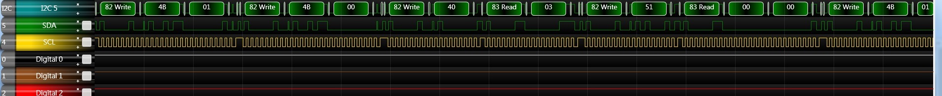
I2C_WriteDeviceRegister(IOE_REG_FIFO_STA,0x01); //IOE_REG_FIFO_STA = 0x4B
start bit -> 0x82(slave address) + W bit -> Send 0x4B 0x01 ->
start bit -> 0x82(slave address) + W bit -> Send 0x4B 0x00 -> ……
實驗二: 兩塊(以上)板子的數據傳輸
一塊板子當作Master,其他的作為Slave,實驗I2C的資料傳輸
slave
git clone https://github.com/colin8930/slave_i2c
cd slave_i2c
make
make flash
master
git clone https://github.com/colin8930/master_i2c
cd master_i2c
make
make flash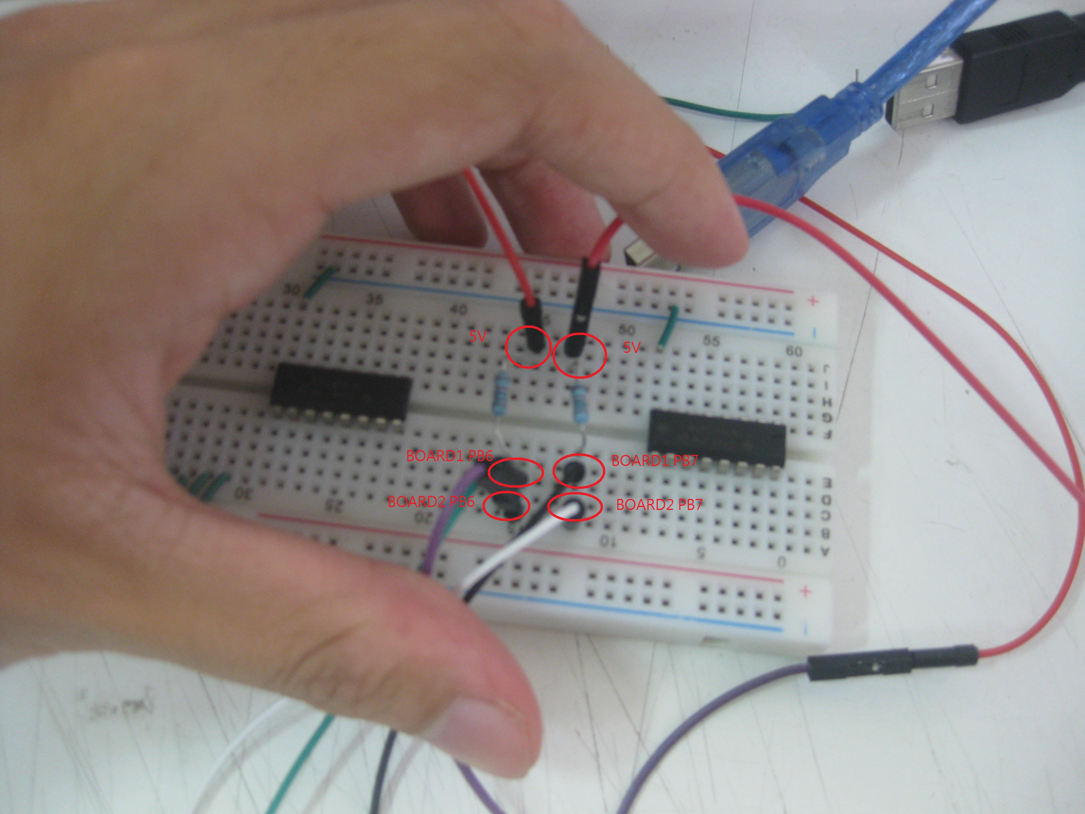
- start bit

- send address
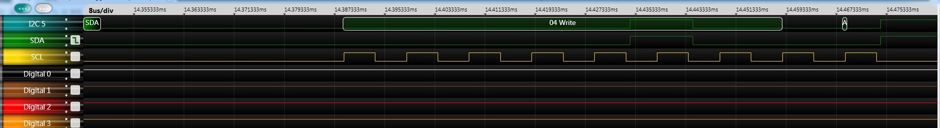
- 0x30
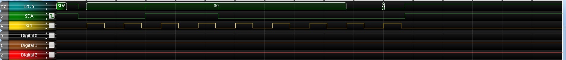
- start bit

- send address
- 0x31
master: - http://youtu.be/Y0udSje3PDc
slave: - http://youtu.be/nAkrzcuHWQU
SMBus
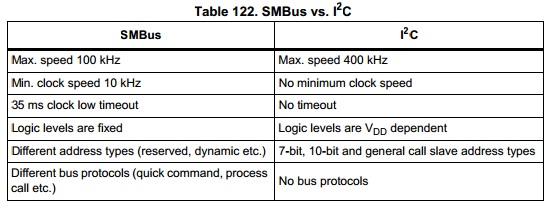
I2C起源於電視設計,但之後朝通用路線發展,各種電子設計都有機會用到I2C;而SMBus則在之後為PC所制訂的先進組態與電源管理介面(Advanced Configuration & Power Interface;ACPI)規範中成為基礎的管理訊息傳遞介面、控制傳遞介面。
在I2C中,主控端要與受控端通訊前,會在匯流排上廣播受控端的位址資訊,每個受控端都會接收到位址資訊,但只有與該位址資訊相切合的受控端會在位址資訊發佈完後發出「已妥」的回應(Acknowledge;ACK),讓主控端知道對應的受控端確實已經備妥,可以進行通訊。但是,I2C並沒有強制規定受控端非要作出回應不可,也可以默不作聲,即便默不作聲,主控端還是會接續工作,開始進行資料傳遞及下達讀/寫指令,如此的機制在一般運用中還是可行,但若是在一些即時(Real Time)性的應用上,任何的動作與機制都有一定的時限要求,這種可有可無式的回應法就會產生問題,可能會導致受控端無法接收資訊。
相同的情形,在SMBus上是不允許受控端在接收位址資訊後卻不發出回應,每次都要回應,為何要強制回應?其實與SMBus的應用息息相關,SMBus上所連接的受控裝置有時是動態加入、動態移除的,例如換裝一顆新電池,或筆記型電腦接上船塢埠等,如果接入的裝置已經改變卻不回應,則主控端的程式所掌握的並非是整體系統的最新組態,就會造成錯誤動作。
- Low Operating Frequency and Timeout:
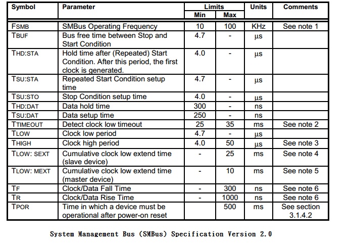
以運作頻率來說,I2C此方面相當寬裕,最低頻可至0Hz(直流狀態,等於時間暫停),高可 100kHz(Standard Mode)、400kHz(Fast Mode)、乃至3.4MHz(High Speed Mode),相對的SMBus就很拘限,最慢不慢於10kHz,最快不快於100kHz。至於為何要維持在10kHz以上,主要的原因是為了管理監控,另一個用意是只要在保持一定傳速運作的情況下加入參數,就可輕鬆獲知匯流排目前是否處於閒置(Idle)中,省去逐一偵測傳輸過程中的停斷(STOP)信號,或持續保有停斷偵測並輔以額外參數偵測,如此對匯流排閒置後 的再取用會更有效快速。
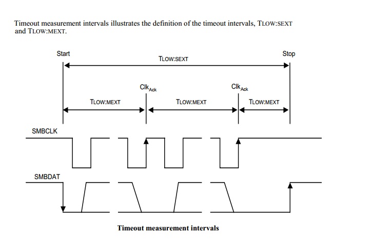
- Clock low extending:
SMBus提供clock同步機制,允許不同速度之設備在共同的bus上,設備可以週期性地延長每個clock cycle,但必須維持fSMB,MIN frequency of 10 KHz ( fSMB,MIN-1= 100µs),以維護SMBus的頻寬

- Different Logic levels
SMbus在能耗上優於I2C
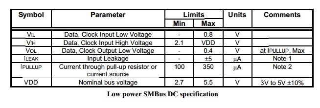
I2C的Hi/Lo邏輯準位有兩種認定法: * 相對認定:相對認定是依據Vdd的電壓來決定,Hi為0.7 Vdd,Lo為0.3 Vdd * 絕對認定:與TTL準位認定相同,直接指定Hi/Li電壓,Hi為3.0V,Lo為1.5V
SMBus只有絕對認定,Hi為2.1V,Lo為0.8V
電流部分,由於SMBus一起頭就是運用在筆記型電腦內,所以低用電的表現優於I2C,只需100uA就能維持工作,I2C卻要到3mA。低用電特性也反應在漏電流(Leakage Current)的要求上,I2C最大的漏電流為10uA,SMBus為5uA。
Different address type:
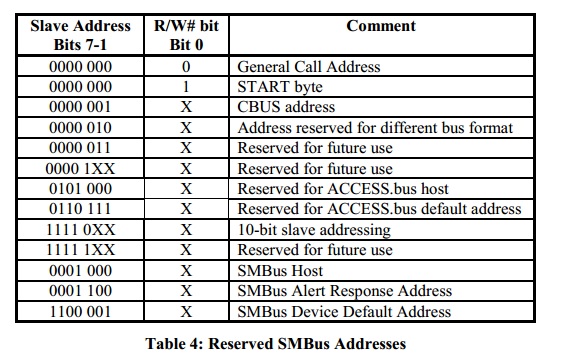
- Reserved addresses
SMBus, Access bus and I2C reserve several addresses for specific bus functions as defined in Table 4.
Table 4.為保留的Slave address,在設備選擇Slave address要避免使用這些address
- Purpose-assigned addresses
這些地址被SMBus分配到特定類型的設備。每個類型設備,可以獲取一個指定的地址,這些地址都必須有一個與之相關SMBus規範(與設備製造商有關)。
- Prototype Addresses
Prototype Addresses保留用於設備與應用程式作為雛型驗證及工程開發,它們永遠不能分配給任何設備

- Miscellaneous device addresses
製造商可能生產製作與 SMBus 相容的設備,他們並不需要完整的SMBus規範。
- Dynamically assigned addresses
SMbus(2.0版本)可透過動態分配給每個Slave一個唯一的adress來解決地址衝突,需遵從ARP(Address Resolution Protocol)地址解析協議
(有關更詳細動態分配部分可參考- reference_manual 5.6章的部分)
- ALERT mechanism:
這必須於時脈線與資料線外再追加一條線(稱為:SMBSUS)才能實現,ALERT雖名為警訊但其實是中斷(Interrupt)的用意,Slave可以將SMBSUS線路的電位拉低(ALERT#,“#”表示低準為有效),這時就等於向Master發出一個中斷警訊,要求Master儘速為某一Slave提供傳輸服務。Master要回應這個服務要求,是透過I2C/SMBus的時脈線與資料線來通訊,但要如何知道此次的通訊只是Master對Slave的一般性通訊?還是特別針對Slave的中斷需求而有的服務回應?
這主要是透過Master發出的位址資訊來區別,若為回應中斷的服務,位址資訊必然是「0001100」,當Slave接收到「0001100」的位址資訊,就知道這是Master特為中斷而提供的服務通訊。因此,韌體工程師須留心,規劃時必須讓所有的Slave都不能佔用「0001100」這個位址,以供ALERT機制運用(當然!若現在與未來都不會用上ALERT機制則可儘管佔用)
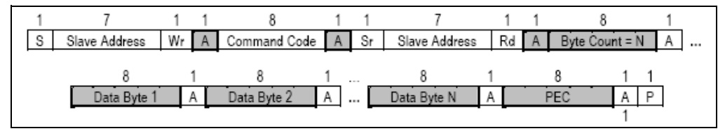
- PEC:
針對傳輸的Data,做CRC8(Cyclic redundancy check 8)的運算,計算範圍從Target Address,到所有資料傳輸結束,有PEC的Packet和沒有PEC的Packet的差別在於最後一個byte
是否傳輸PEC byte.
PEC的BUS協議:- reference_manual 5.5章的部分
-補充-:CRC演算法
用來檢查資料是否有問題的方法,把資料轉成一多項式,再用另一固定自選多項式進行除法後所得到餘數比對,最後檢查是否和預定值相同
CRC演算法:- WIKI-循環冗餘校驗
PMBUS
PMBus(Power Management Bus),是一種數位電源管理協議標準,使電源轉換器與其他設備方便溝通的一個協議,PMBus是由SMBus(1.1版)延伸而來,保有SMBus 1.1版的功能及新增了一些功能(但不支援timeout)。
一個典型的PMBus連接方式
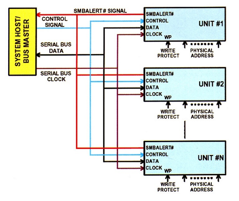
PMBus協議規定所有slave device必須將其默認的配置數據保存在永久性存儲器內,這樣它們在上電時無須再與BUS通信跟SMBus比較起來,PMBus多了兩種與Power converter共用的兩種hardware signal,一個是Control Line,用於啟動或關閉單個slave device,另一個是write protect用於防止更改到永久性儲存器的內容。
此外PMBus還新增了BLOCK_WRITE_BLOCK_READ_PROCESS_CALL和GROUP_COMMAND_PROTOCOL
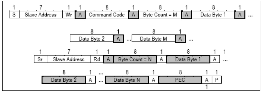
Block Write跟Group_command protocol(基於PIC16F886這個PMBus device)如下所示:
Block Write
Group_Command_Protocol